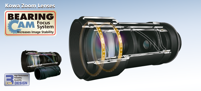
New Technology Bearing CAM Focus System

Bearing CAM Focus System

Conventional zoom lenses commonly employ a helicoid system for the focus mechanism, which is essentially an internal screw type device that allows the user to twist the lens into focus. However, one of the main problems with a helicoid system is that environmental factors such as cold temperatures can make the focus torque too heavy for any parts to move freely without strong force.


To help prevent such problems from occurring, Kowa developed a "3-CAM" system for use in all of its varifocal and zoom lenses. Kowa's innovative 3-CAM design utilizes guide pins to minimize the contact points of all the internal mechanical parts so that they move freely with significantly less friction and torque. In other words, the result you get is a more robust lens with a longer product life since the 3-CAM system reduces wear and tear of all moving parts. The 3-CAM system also increases optical performance by solving the problem of de-centering, decreases internal reflection, and reduces the need for grease on the focus and zoom mechanisms.


In an effort to further improve on the 3-CAM technology, Kowa has designed a "Bearing CAM" focus system for the internal moving mechanisms of our zoom lenses.
This new Bearing CAM focus system is especially important for long range zoom lenses because the heavy weight and large diameter of such lenses can push down on the internal moving parts. If the pressure on such lenses gets to be too much, the inside barrel can become deformed, thus changing the alignment of the optical path. Kowa's Bearing CAM focus system helps to resolve this issue because it uses dozens of ball bearings to absorb extra pressure and at the same time, allows for a smoother rotation of moving parts. What this translates to is that you get a lens with an even longer product life that is more resilient against frequent focus and zoom movement.


Kowa has released a high definition 2 megapixel 20-750mm LMZ20750AMPDC-XF long range zoom lens with the new Bearing CAM focus system.

Technical Data

Wiring Diagram for Motorized Zoom Auto Iris Lenses

N.B.
The following are wiring diagrams of our standard models. For other detailed information, see the instruction manual in individual box.

Auto iris with Motorized Zoom, Focus (AM Type)

Auto iris with Motorized Zoom, Focus (AM Type)

AI, Motorized Zoom with Preset on Zoom, Focus (AMP Type)

AI, Motorized Zoom with Preset on Zoom, Focus (AMP Type)

Motorized Zoom 3 Motor Type (M3P Type)

Motorized Zoom 3 Motor Type (M3P Type)

Selection Guide for CCTV Lenses

  1. 1. Angle of View and Field of View

    • The angle of view can be obtained by following formula. θ=2tan-1 h/2f
    • The Field of View can be obtained by following formula. H=h L/f
  2. 2. F-Number

    The F-number is an index of the amount of light that passes through a lens. The smaller the number, the greater the amount of light. The relationship between the F-Number, focal length, and effective diameter can be calculated by the following formula. F-number=f/A Where f=focal length, and A=effective diameter
  3. 3.Image Format Size (unit:mm)

    • Image sensor sizes are in a ratio of 1 : 0.69 : 0.5 : 0.38 i.e. 1/2"format is 50% of 1" format, 1/2" format is 75% of 2/3" format, 1/3" format is 75% of 1/2" format.
    • Even when the same lens is used, angles of view vary in terms of ratio between image sensor sizes. The smaller the format, the narrower the angle of view for any given lens.
    • When using a 1/2" lens for a 1/3" camera, the correlation list the right may help to select a 1/2" lens with an angle of view similar to that of a 1/3" lens.
    Focal length of 1/2" lens Focal length of 1/3" lens
    f=4mm f=3mm(2.8mm)
    f=6mm f=4.5mm
    f=12mm f=9mm(8mm)
  4. 4. Flange Back & Back Focal Length

    • Flange Back. The distance from a basic plane of a mount to a Focal Plane. The Flange Back of each mount is standardized as follows:
      C mount : 17.526mm CS mount : 12.5mm
    • Back Focal Length. The distance from a center of a rear lens to a Focal Plane. When a lens is attached to a camera, the back focal length may be a standard to judge whether an end of rear lens hits any mechanical parts inside a camera.
    • Mechanical Back Focal Length. The distance from any closest parts of a lens to a Focal Plane. When a lens is attached to a camera, the Mechanical Back Focal Length may be astandard to judge whether any rear parts of lens hits any mechanical parts inside a camera.
  5. 5. C Mount and CS Mount

    Compatibility
      C Mount Camera CS Mount Camera
    C Mount Lens OK OK
    CS Mount Lens NO OK

    When using a C mount lens for a CS mount camera, attach a C/CS mount adapter (thickness 5mm) between the lens and camera.

    C / CS MOUNT LENS (unit:mm)